Talk to an Expert

LET'S TALK

Back to All News

Flex Rigid PCBs: Why You Should Use Them

Yaad Eliya

|

13th January ,2025


Introduction

The flexible substrate functionality of Rigid-Flex or Flex Rigid PCBs offers greater spatial efficiency in achieving sub-compact packaging at a significantly reduced product weight. Designed in a 3D space, flexible board substrates can twist, fold, and roll into almost any desired shape and size to accommodate final package placement. The Rigid-Flex materials consist of polyimide on a Cu cladding substrate connected to an FR4 rigid board. Most Rigid-Flex boards feature multiple layers of flexible circuit substrates with via-hole interconnects and can be attached both externally or internally to one or more rigid boards. Driven by its unique advantages in size, weight, flexibility, and performance, market demand for Rigid-Flex PCBs is strong and growing.

What Are Rigid-Flex PCBs?

Rigid-Flex PCBs combine the best features of both rigid and flexible PCBs into a single unit, integrating rigid segments for structural stability with flexible layers that provide the versatility to accommodate complex geometries. Unlike traditional PCBs, which are confined to a two-dimensional layout , Rigid-Flex PCBs allow seamless electrical and mechanical connections in three-dimensional spaces. This hybrid design minimizes the need for multiple components, reduces weight, and enhances reliability by eliminating common failure points.

Key Advantages of Rigid-Flex PCBs

1. High Reliability

Rigid-Flex PCBs reduce the need for board-to-board connectors and solder joints, common failure points in traditional designs. This inherent reliability makes them ideal for critical applications where performance and durability are paramount.

2. Miniaturization

The ability to bend, fold, and twist into compact spaces allows Rigid-Flex PCBs to replace multiple connectors and wire harnesses with a single integrated unit. This capability has revolutionized the design of portable and wearable electronics, including laptops, cameras, robotics, automotive systems, and medical devices.

3. Enabling  Hybrid Structures

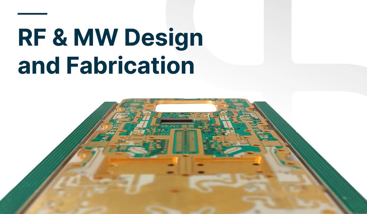
Implementing a hybrid structure, with RF/MW materials in outer layers and DC in inner layers, with FR4/POLYIMIDE at the core of the layer structure, enables miniaturization, reduces size and weight, and enhances electrical performance.

Rigid-flex layer structure, entirely suitable for RF, MW, with low dielectric constants of raw materials, DK= 3.5, 3.3, 3.0

4. Enhanced Testing and Integration

Since interconnections are tested at the PCB manufacturing level, Rigid-Flex PCBs simplify system integration and testing. Subcircuits can be connected seamlessly to the main design, enabling automated testing processes and reducing development timelines.

5. Cost Efficiency

By integrating flexible circuits with rigid boards, Rigid-Flex PCBs reduce the number of components and assembly steps required, lowering overall manufacturing costs. They provide the flexibility of a flex circuit at a cost closer to that of rigid PCBs.

6. Durability in Extreme Environments

Rigid-Flex PCBs are well-suited for challenging environments where mechanical stress, temperature fluctuations, or vibrations could compromise traditional PCBs. Their robust design ensures reliable operation in demanding conditions.
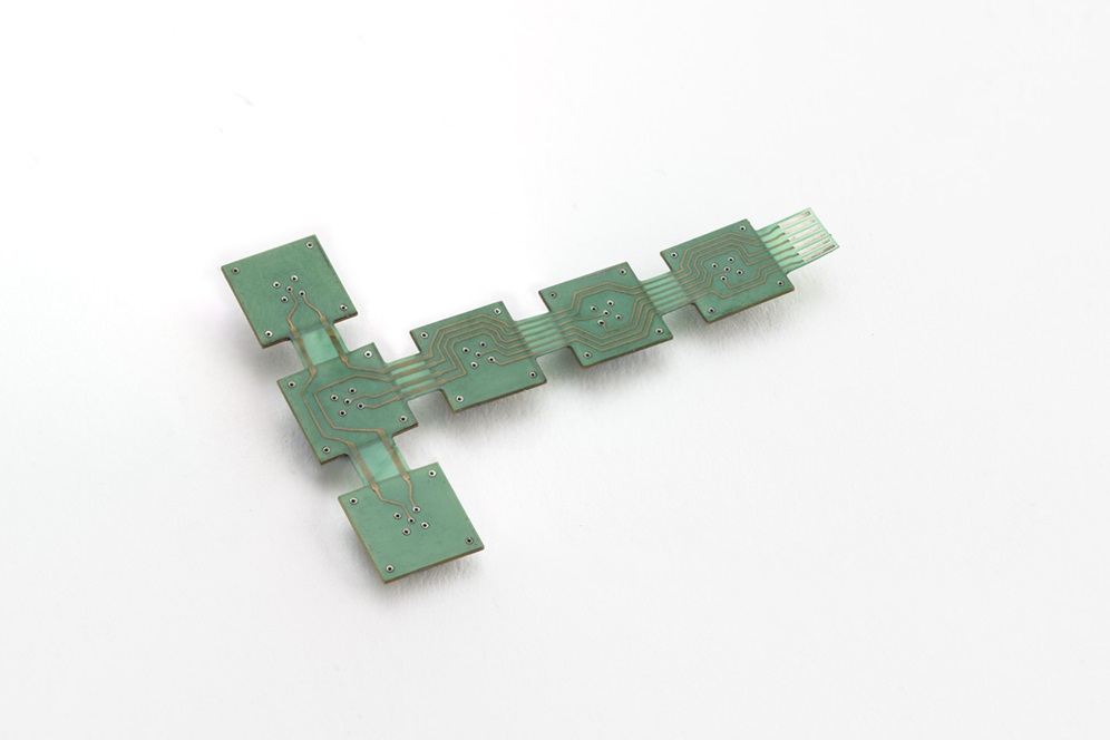
Flex Rigid PCB:

Unique Technical Features and Design Characteristics

    • Layered Construction: Multiple flexible layers interconnected with vias can be incorporated into the rigid sections, enabling high-density interconnections.
    • Material Synergy: Polyimide in flexible sections provides excellent heat resistance and dielectric strength, while FR4 in rigid sections ensures mechanical stability.
    • 3D Design Capability: Enables complex geometries and efficient use of space, essential for modern compact devices.
    • Thermal Management: Advanced thermal management options, including integration with low CTE substrates, ensure reliability under extreme operating conditions.

Applications Across Industries

The versatility of Rigid-Flex PCBs has driven their adoption across a wide range of industries:

    • Consumer Electronics: Compact devices like smartphones, tablets, and wearables benefit from the space-saving and lightweight properties of Rigid-Flex PCBs.
    • Wearable Devices: Sport devices such as fitness trackers, smartwatches leverage the flexibility and durability of Rigid-Flex PCBs to ensure reliability and comfort.
    • Automotive: Essential for advanced driver-assistance systems (ADAS), infotainment systems, and electric vehicle power management.
    • Medical Devices: From implantable devices to diagnostic equipment, Rigid-Flex PCBs enable miniaturization and reliability in life-critical applications.
    • Aerospace and Defense: Withstand extreme conditions while providing reliable performance for avionics, navigation systems, and military-grade equipment.
    • Industrial Automation: Enable robust and compact designs for robotics, sensors, and control systems.
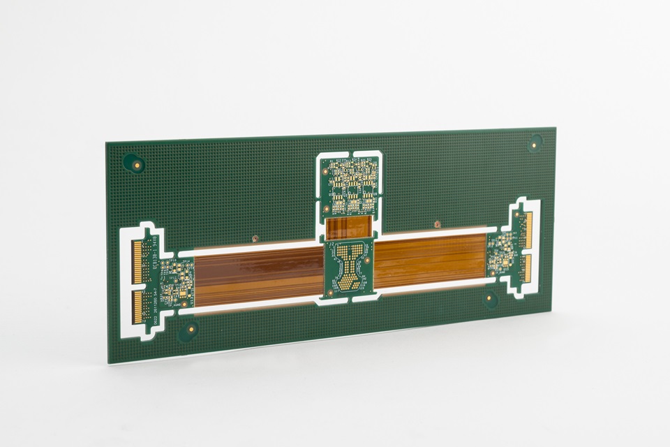
Flex Rigid PCB

Manufacturing Technology and Processes

The manufacturing of Rigid-Flex PCBs involves precise engineering and strict quality controls to ensure reliability and performance:

  1. Material Selection: Choosing the right combination of polyimide, copper cladding, and FR4 materials to meet specific design requirements.
  2. Lamination: Flexible and rigid layers are laminated together, requiring careful alignment to avoid warping or misalignment.
  3. Drilling and Via Formation: Accurate drilling ensures reliable electrical connections between layers.
  4. Etching and Plating: The circuit patterns are etched, and vias are plated for electrical conductivity.
  5. Testing: Extensive electrical and mechanical testing is performed to validate functionality and durability.

Looking Ahead: Emerging Trends

The future of Rigid-Flex PCBs lies in their continued evolution to meet the demands of emerging technologies. Advancements in 3D IC packaging, miniaturization, and higher-density designs are driving innovation. Applications in IoT, 5G, and advanced medical diagnostics are expected to expand, further solidifying the role of Rigid-Flex PCBs in next-generation electronics.

Why Choose PCB Technologies?

PCB Technologies is a leading expert in advanced PCB solutions, specializing in Rigid-Flex, HDI, and RF PCB manufacturing. All materials and structures undergo rigorous testing in our internal reliability laboratory. When a design presents challenges related to reliability or manufacturability, we proactively identify potential issues and recommend optimal alternatives based on specific system requirements, including environmental conditions, vibration profiles, thermal cycling, and other critical parameters. PCB Technologies remains committed to helping you achieve your goals with precision and excellence.

Frequently Asked Questions

What are the primary material considerations for Rigid-Flex PCBs, especially concerning high-frequency performance and thermal management?

Frame-10

Rigid-Flex PCBs typically utilize polyimide for flexible sections and FR4 for rigid sections. For high-frequency applications, engineers should prioritize flexible dielectric materials with low dielectric constants (Dk) and low dissipation factors (Df), such as specific grades of polyimide (e.g., those with Dk values  3.0-3.5) or specialized materials like PTFE or LCP for frequencies exceeding 10 GHz. These materials minimize signal loss and maintain impedance control. For enhanced thermal management, particularly in high-power applications, integrating low Coefficient of Thermal Expansion (CTE) substrates and incorporating thermal vias or heat sinks within the rigid sections is crucial. This mitigates thermal stress and ensures reliability under extreme operating conditions.

How do Rigid-Flex PCBs achieve miniaturization beyond simply combining rigid and flexible elements, and what are the associated design challenges?

Frame-10

Miniaturization in Rigid-Flex PCBs is achieved through their inherent 3D design capability, allowing for intricate folding, twisting, and stacking that eliminates bulky connectors and wire harnesses. This enables sub-compact packaging and a significant reduction in weight. Key design challenges include maintaining precise bend radii to prevent material fatigue (typically 6-10 times the flex layer thickness, or more for dynamic applications), managing layer stack-up transitions between rigid and flexible areas, and optimizing trace routing to minimize stress concentrations. Engineers must also consider localized heat dissipation in tightly packed areas and potential impedance mismatches at the rigid-flex interfaces for high-speed signals.

Can Rigid-Flex PCBs reliably integrate RF/Microwave functionalities, and what specific design techniques are critical for such hybrid structures?

Frame-10

Yes, Rigid-Flex PCBs are well-suited for RF/Microwave applications, especially with the implementation of hybrid structures. This involves strategically placing RF/Microwave materials (e.g., low Dk/Df laminates) in outer layers where signal integrity is paramount, while DC and control circuitry can reside on FR4/polyimide core layers. Critical design techniques include controlled impedance routing (e.g., microstrip or stripline designs), careful selection of low-loss dielectric materials, minimizing discontinuities at the rigid-flex transitions, and employing proper shielding techniques like grounded copper planes to reduce electromagnetic interference (EMI) and crosstalk. Rolled annealed copper foil is often preferred for flexible layers due to its molecular structure and smoother surface, which reduces signal attenuation at high frequencies.

What are the key manufacturing process considerations and challenges unique to Rigid-Flex PCBs compared to traditional rigid PCBs?

Frame-10

The manufacturing of Rigid-Flex PCBs involves several unique challenges. Material selection and precise lamination are critical, as different materials (polyimide, FR4, copper cladding, adhesives) have varying thermal expansion coefficients, which can lead to warping or delamination during high-temperature processing. Accurate drilling and via formation, particularly for microvias in high-density interconnect (HDI) designs, are more complex due to the varying material properties across the rigid and flexible sections. Etching and plating processes require fine control to maintain critical trace widths and spaces across both sections. Furthermore, rigorous testing, including dynamic bend cycle testing and thermal shock testing, is essential to validate the long-term reliability of the hybrid structure.

How do Rigid-Flex PCBs enhance overall system reliability and testing procedures in complex electronic assemblies?

Frame-10

Rigid-Flex PCBs significantly enhance system reliability by reducing the number of discrete components, such as board-to-board connectors and wire harnesses, which are common points of failure due to solder joint fatigue or mechanical stress. This integration streamlines the assembly process, minimizing manual handling and potential errors. For testing, interconnections are largely verified at the board manufacturing level. This allows for more comprehensive automated electrical and functional testing of subcircuits before final system integration, reducing development timelines and simplifying troubleshooting in complex assemblies.

Please present the thermal management options in Rigid-Flex PCBs. How are coefficient of thermal expansion (CTE) mismatches addressed?

Frame-10

Thermal management in Rigid-Flex PCBs is crucial, particularly as devices become more compact and power-dense. Advanced options include the strategic placement of high-thermally-conductive materials (e.g., metal cores or specialized laminates) within the rigid sections, along with the use of thermal vias to conduct heat away from critical components to heat sinks or larger copper planes. Addressing CTE mismatches between polyimide (flexible) and FR4 (rigid) is vital to prevent delamination and stress. We mitigate this through careful material selection, optimized layer stack-ups, and controlled lamination processes. Low-flow or no-flow prepregs are used to minimize resin movement and stress during lamination.

In what scenarios do the cost efficiencies of Rigid-Flex PCBs truly manifest?

Frame-10

While the initial manufacturing cost of Rigid-Flex PCBs can be higher due to specialized materials and processes, their cost efficiencies manifest significantly in the overall product lifecycle. These savings stem from several factors: reduced bill of materials (BOM) by eliminating multiple PCBs for a single device, numerous connectors and cables, lower assembly costs due to a single, integrated unit, reduced labor for manual wiring, and improved reliability leading to fewer warranty claims and repairs. For complex, miniaturized, or high-performance systems where space, weight, and long-term durability are critical, the total cost of ownership often makes Rigid-Flex PCBs a more economically viable solution compared to designs using multiple rigid boards connected by wires.

Please describe emerging trends in PCB technology, such as 3D IC packaging, and how they are driving adoption of Rigid-Flex PCBs?

Frame-10

Emerging trends like 3D IC packaging, ultra-miniaturization, and the demands of high-speed communication technologies (e.g., 5G, IoT) are significantly driving the evolution of Rigid-Flex PCBs. In 3D IC packaging, Rigid-Flex can provide the necessary interconnections between stacked dies and external components in a compact, conformable package. Their ability to integrate high-frequency materials makes them ideal for 5G modules requiring high signal integrity and reduced form factors. Advancements in flexible substrate materials with even lower Dk/Df, finer line and space capabilities, and improved thermal conductivity are continuously expanding the application range of Rigid-Flex PCBs in these cutting-edge fields.

You May Also be Interested in

This website uses cookies to enhance the user experience.

Decline

Thank you

We will contact you shortly