Transitioning from HTE to RTF Copper Foil in PCB Manufacturing
Yaad Eliya – CTO, PWB Division
|18th June ,2025
Risks, Benefits, and Best Practices
Abstract
As PCB technologies advance to support higher data rates, finer features, and improved reliability, the materials used must also evolve. A critical material consideration is whether to continue using High-Temperature Electrolytic (HTE) copper foil or transition to Reverse Treated Foil (RTF) in both core and outer layers. This article provides PCB designers, layout engineers, and manufacturing professionals with a practical, risk-aware guide to evaluating and implementing RTF copper—particularly for legacy, proven designs.
-
Background: HTE vs. RTF Copper Foil
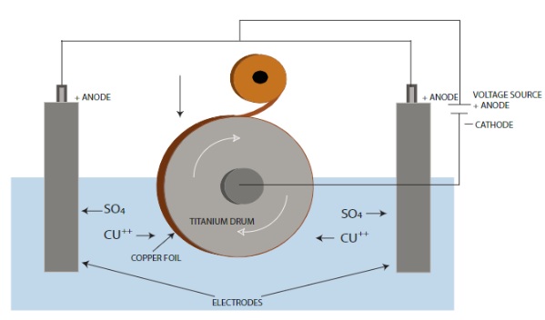
HTE (High-Temperature Electrolytic) copper foil has long been the standard in PCB fabrication, valued for its roughened matte side that ensures strong prepreg adhesion and process compatibility across many fabrication lines.
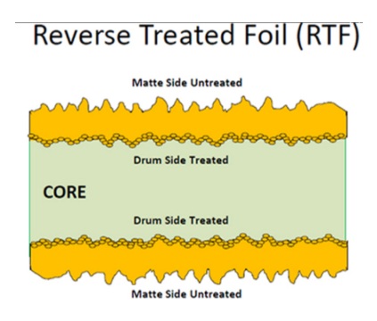
RTF (Reverse Treated Foil) represents a modern refinement. By roughening the drum side (rather than the signal side), RTF offers improved signal performance, especially for high-frequency applications.
Copper Foil Comparison
| Property | HTE Copper Foil | RTF Copper Foil |
| Surface Roughness | Rougher | Smoother (Signal Side) |
| Signal Integrity (HF) | Moderate | High |
| Peel Strength | Very Good | Good |
| Etching Precision | Moderate | High |
| Availability in Core | High | Moderate |
| Cost | Lower | Higher |
RTF foil is already in use for many high-speed commercial and defense applications. It is a proven, reliable technology—but one that must be implemented with care and awareness.
2. Use Case: Replacing HTE with RTF in Repeat Production
Many organizations consider transitioning to RTF not to innovate, but to align with supplier changes or to improve long-term reliability. Here’s how to manage the switch without compromising performance.
2.1 Electrical Considerations
-
-
Impedance Shift: The smoother signal surface of RTF slightly reduces impedance (~3–6%). This can be predicted through simulation and compensated by adjusting trace width.
-
Signal Integrity: RTF enhances insertion loss performance and reduces noise coupling in high-frequency designs (e.g., DDR4/5, PCIe Gen 4/5, RF).
-
EMC Behavior: Lower surface reflection and well-defined return paths can improve EMI margins.
-
2.2 Process Compatibility
-
-
Lamination: RTF may require slight adjustments in lamination cycles. Most modern PCB fabs support this with standard press profiles.
-
Etching: RTF supports more precise etching. Designers using LDI tools typically do not need to modify photo tools.
-
Availability & Cost: While RTF materials are still costlier and less available than HTE, the gap is narrowing rapidly—especially among reliable suppliers.
-
-
Managing Risk in Legacy Stack-ups
When approving RTF for legacy stackups, consider the following manageable risks:
-
- Impedance Failures: Preventable with updated simulations and TDR testing.
- Delamination: Unlikely, assuming IPC-recommended lamination cycles and peel strength standards are followed.
- EMI Changes: Potential improvements, though analog/RF designs should be re-characterized.
-
Transition Strategy: Step-by-Step Validation
To reduce risk, follow this structured implementation plan:
Signal Integrity Validation
-
- Simulate using RTF roughness values from vendor datasheets (e.g., Isola, Panasonic).
- Validate stackup using TDR or VNA in pilot runs.
Pilot Qualification
-
- Produce 3–5 boards using RTF in the current stackup.
- Run full PCBA reflow and functional tests, comparing performance with legacy versions.
Lamination Review
-
- Request updated lamination profiles from the PCB supplier.
- Confirm compliance with IPC-TM-650 peel strength standards.
Change Control
-
- Document the change via MCN (Material Change Notice).
- Include simulation results, process changes, and reliability validation.
-
Standards & Resources
-
- IPC-4101 – Differentiates copper foil types and material slash sheets
- IPC-TM-650 – Details test methods for peel strength and surface roughness
- Simulation Tools – Polar Si9000, Ansys HFSS
- Vendor Data – Dk/Df values, roughness profiles, stackup guidance
-
Final Thoughts: A Smart, Safe Upgrade
Though changing materials in a validated stack-up may raise concerns, the switch from HTE to RTF offers measurable electrical performance gains and long-term process benefits. With proper simulation, validation, and documentation, this upgrade can modernize your existing designs—while maintaining, or even improving, quality and reliability.
Author Bio: Yaad Eliya

-
- CTO at PCB Technologies with over 20 years of experience
- Expert in electronic materials, particularly in rigid-flex, RF, and microwave applications
- Leads special application developments for medical, space, and defense markets
- Specialist in “tailor-made” design-stage solutions in collaboration with customer R&D teams